


The Fundamentals of RF Directional Couplers and How to Use Them Effectively
 Radio frequency (RF) applications like automotive radar, 5G cellular, IoT and others are expanding the number of RF sources used in electronic systems. All of these sources require a methodology for monitoring and controlling RF power levels while at the same time not incurring losses in the transmission line and load. Also, some applications require high power transmitter output, so designers need to figure out a way to monitor output signals without directly connecting sensitive instrumentation that may be damaged by high signal levels.
There are other challenges, such as how to determine the characteristics of an RF load like an antenna over a wide frequency range, as well as how to monitor load variations and standing wave ratio while the transmitter is on-air to prevent high reflected power and amplifier damage.
The solution to these requirements and challenges lies in directional couplers, inserted in a transmission line. These permit precise monitoring of the RF energy flow in the line while reducing power levels by a known, fixed amount. Directional couplers introduce minimal disturbances of the main line signal in the sampling process. They are able to differentiate between forward and reflected power, and permit monitoring of return loss or standing wave ratio providing feedback of load changes while on-air.
This article discusses the operation of directional couplers and introduces three topologies and appropriate examples from Anaren, M/A-Com, and Analog Devices. It then examines their typical characteristics and shows how to use them effectively.
What is a directional coupler?
A directional coupler is a measurement device that is inserted into the transmission line between an RF source—such as a signal generator, vector network analyzer, or transmitter—and a load. It measures both the RF power from the source to the load—the forward component—as well as the reflected component, power reflected back from the load to the source. Knowing the forward and reflected components permits the computation of total power, return loss, and standing wave ratio of the load.
Directional couplers are four-port circuits that are configured as three or four-terminal devices (Figure 1).

Figure 1: The schematic symbols for both a three-port (left) and four-port directional coupler (right). (Image source: Digi-Key Electronics)
The source is generally connected to the coupler’s input port and the load to the output or transmitted port. The coupled port output is an attenuated version of the forward signal. The attenuation value may be indicated as shown in the three-port example. The isolated port terminated internally in the three-port version is brought out in the four-port version and its output is proportional to the reflected signal. Arrows within the schematic symbol indicate the component path. For example, in the four-port configuration, the input port is directed to the coupled port indicating that it receives the forward component, while the output port is linked to the isolated port which reads the reflected signal. Port numbers are not standardized and will vary from manufacturer to manufacturer. Port nomenclature is more uniform among suppliers.
Couplers are symmetrical devices and connections can be reversed. In the case of the three-port device, reversing the input and output ports will cause port three to be the isolated port. In the four-port device, reversing the input and output ports results in the coupled and isolated ports being exchanged.
The outputs of the coupler are RF signals. The outputs of the coupled and isolated ports are usually connected to a peak or RMS detector, which produces a baseband signal related to the forward and reflected power levels. The combination of the directional coupler and associated detectors is called a reflectometer.
In some instances, two directional couplers are connected back-to-back, forming a dual directional coupler. This is done to minimize leakage between the coupled and isolated port.
Directional coupler specifications
Directional couplers are specified by several key characteristics including bandwidth, rated input power, insertion loss, frequency flatness, coupling coefficient, directivity, isolation, and residual voltage standing wave ratio (VSWR).
-
Bandwidth: The coupler’s bandwidth indicates the range of frequencies, in hertz, over which the coupler is designed to work within its specifications.
-
Rated input power: Couplers have a maximum input power rating, expressed in watts, both for continuous wave (CW) and pulsed input signals. These are the maximum power levels that the device can handle without degradation of performance or physical damage.
-
Insertion Loss: Describes the power loss, expressed in decibels (dB), due to the insertion of the device into the main transmission path.
-
Frequency flatness: Frequency flatness specifies the variation in amplitude response of the main transmission path, in dB, over the device’s specified bandwidth as a function of variation in the input signal’s frequency.
-
Coupling coefficient or coupling factor: The coupling coefficient is the ratio of the input power to the power at the coupled port, in dB, when the coupler is properly terminated at all ports. This is one of the prime characteristics of the directional coupler. The output of the coupled port is proportional to the power level in the direct path from input to output by this known factor. The coupled output can be connected to other instrumentation, like an oscilloscope, without the danger of overloading the instrument.
-
Isolation: The ratio, in dB, of the power at the input port and at the isolated port with all ports properly terminated.
-
Directivity: The ratio in dB of the power at the coupled port to the power at the isolated port with all ports properly terminated. In the case of a three-port coupler, two power measurements are made: one in the normal forward direction and one with the input and output ports reversed. This specification is a measure of the separation of the forward and reflected components; generally, the higher the directivity the better the performance of the coupler. Directivity cannot be measured directly but is computed based on the isolation and reversed isolation measurements.
-
Residual VSWR: The standing wave ratio measured with the coupler properly terminated at all ports. This is a measure of the coupler’s inherent impedance match.
Directional coupler topologies
Directional coupler designs can be executed in several ways. The three most common topologies are RF transformer, resistive bridged, or coupled transmission lines. The RF transformer-based topology uses two RF transformers (Figure 2). Here, transformer T1 senses the main line current between the input and the load. A second transformer, T2, senses the voltage on the main line relative to ground. The coupling factor is controlled by the transformer turns ratio, N.

Figure 2: The RF transformer-based directional coupler topology uses two RF transformers to sense both the forward and reflected components on the main line. (Image source: Digi-Key Electronics)
The theoretical operation of this type of directional coupler can be analyzed by combining the voltages induced on the coupled line by each transformer individually and then adding the results (Figure 3). Vin is the forward voltage and VL is the reflected voltage.

Figure 3: Analysis of the transformer-based coupler by analyzing the voltage contribution of both transformers to the coupled line individually. (Image source: Digi-Key Electronics)
The contribution of the current sense transformer to the coupled line for the coupled (VF’) and Isolated port (VR’) is calculated in the upper diagram with the voltage sensing transformer removed from the diagram. Similarly, the contribution to those ports from the voltage sensing transformer with the current sensing transformer removed are computed in the lower as VF” and VR”. The voltage at the coupled port, VF, is determined by adding VF’ and VF”:
VF = VF’ + VF’’ = (VIn – VL)/2*N + (VIn + VL)/2*N = VIn/N
Equation 1
The resulting voltage at the coupled port is the input voltage divided by the transformer turns ratio.
Likewise, combining VR’ and VR” yields the voltage at the isolated port:
VR = VR’ + VR’’= (VIn – VL)/2*N – (VIn + VL)/2*N = –VL/N
Equation 2
The voltage at the isolated port is minus the reflected voltage divided by the transformer turns ratio. The negative sign shows that the reflected voltage is 180° out of phase with the forward voltage.
Performance of this type of directional coupler is good over a broad frequency range as seen in the M/A-Com MACP-011045, which has a bandwidth extending from 5 to 1225 megahertz (MHz). This transformer-based coupler has a coupling factor of 23 dB and a power rating of 10 watts. Isolation is frequency dependent varying from 45 dB for frequencies under 30 MHz to 27 dB above 1 gigahertz (GHz). It uses a surface mount package with dimensions of 6.35 millimeters (mm) x 7.11 mm x 4.1 mm making it compatible with most wireless applications.
Coupled transmission line-based couplers are based on coaxial cables or printed circuit transmission lines. The mechanism places two or more transmission lines, usually a quarter wave in length, in close proximity so that a small, controlled, amount of the signal power leaks from the main line to one or more coupled lines (Figure 4).

Figure 4: An example of a dual directional coupler using coupled transmission lines. Lines are usually quarter wavelength sections at the designed center frequency. (Image source: Digi-Key Electronics)
The input is applied to port 1 and most of the power is delivered to the load on port 2. A small amount of power is coupled to the secondary lines connected to ports 3 and 4. Port 3 is the coupled port. The power level there is a fixed percentage of the applied power. The coupling coefficient, a function of the geometry of the coupled lines, describes the power at the coupled port. Reflected power is coupled to port 4, the isolated port.
The Anaren 11302-20 is a typical coupled transmission line directional coupler covering a frequency range of 190 to 400 MHz capable of handling up to 100 watts. It provides a nominal coupling factor of 20 dB with an insertion loss of 0.3 dB. It is contained in a 16.51 x 12.19 x 3.58 mm surface mount package and is intended for monitoring power level and VSWR measurements for moderate power transmitters. The dimensions for this type of coupler are related to the frequency range. As the operational frequency decreases the length must increase. They are generally used for UHF and higher frequencies where the dimensions can be smaller.
The last directional coupler topology is the directional bridge, a circuit related to the classical Wheatstone bridge. This topology is used with the Analog Devices ADL5920 RMS and VSWR detector (Figure 5).

Figure 5: A simplified schematic of the bidirectional bridge used in the Analog Devices ADL5920 RMS and VSWR detector. The calculation shown derives a directivity of 33 dB based on analysis of a properly terminated condition. (Image source: Analog Devices)
The ADL5920 uses a resistive bridge to separate the forward and reflected voltages in a transmission line. The calculation shown computes the theoretical directivity of the device for low frequencies with the rated termination. The result is a directivity of 33 dB. The VREV and VFWD outputs from the bridge are fed to RMS detector stages with 60 dB of dynamic range. The detector outputs read linearly in dB. A third output derived from the difference of the forward and reflected outputs produces a voltage proportional to the return loss in dB. The bridge-based coupler covers a frequency range of from 9 kHz to 7 GHz with a power rating of 33 dBm (2 watts) for a 50 ohm (Ω) matched load. Insertion loss varies from 0.9 dB at 10 MHz to 2 dB at 7 GHz. The device is packaged in a 5 x 5 mm surface mount package with a thickness of 0.75 mm.
Analog Devices supplies an evaluation board for the ADL5920, the ADL5920-EVALZ. It is fully populated and requires a 5 volt, 200 milliamp (mA) power source. Inputs and outputs are available via 2.92 mm connectors, as are the primary outputs. The schematic shows typical connections required for the ADL5920 (Figure 6). This is an ideal tool for trying the ADL5920 with minimal effort.
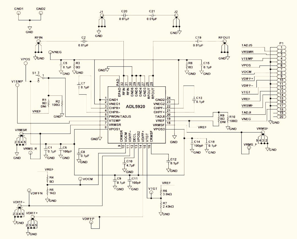
Figure 6: The schematic for the ADL5920-EALZ evaluation board shows typical connections required for the Analog Devices ADL5920 bidirectional RMS and VSWR detector. (Image source: Analog Devices)
The resistive bridge implementation of the directional coupler offers the broadest frequency range, getting very close to direct current (DC). The transformer and transmission line versions have more restrictive bandwidths but are both capable of higher power limits.
Any of these devices can be used to tap off a sample of the input power for use in signal monitoring circuits. The resulting sample can be measured to determine the power level, frequency, and modulation using traditional instruments such as an oscilloscope or spectrum analyzer. The data can also be integrated as part of a feedback loop that adjusts the output to keep it within desired limits.
Conditions at the load are indicated by the voltage standing wave ratio (VSWR). The VSWR of the load at the output port can be calculated by using both the coupled port and the isolated port outputs, which represent the forward and reflected voltages, respectively.
VSWR = (VFWD + VREF)/ (VFWD – VREF)
Equation 3
Return loss can be calculated from the VSWR:
Return Loss (dB) = –20Log10 ((VSWR–1)/(VSWR+1))
Equation 4
Conclusion
The directional coupler is a useful measuring device for RF system designers. It not only provides an amplitude scaled view of RF power levels but also separates the forward and reflected signal components helping to characterize the load. As shown, three commonly used coupler topologies are available that provide these outputs in small packages compatible with wireless devices.