


Get a BLDC Motor Up and Running in Under an Hour with a Hardware-Software Combo
 There are many applications in the defense, industrial, and robotics industries that require an embedded system to use a brushless DC (BLDC) motor. While spinning a motor might seem trivial, it is it is a complex matter that can slow down a project as the developer comes up to speed on motor drive, torque, electrical characteristics, and electromagnetic properties, as well as current feedback measurements.
This assumes they have already selected the appropriate hardware upon which to run the algorithm that will drive the motor with smooth control over the application’s full range of motion, with minimal component count.
What’s needed is a shortcut in the form of an all-in-one hardware and software package that can greatly reduce development time and allow developers to focus on the end application, without getting too deep into the fine art of motor control.
This article will introduce one such package from Texas Instruments that combines its microcontroller and development kit hardware with its InstaSPIN™ field-oriented motor control software and tools. It then shows how the combination can be used by a developer new to the field to easily determine motor parameters and get a complex BLDC motor spinning in less than an hour.
What is InstaSPIN-FOC and is it really so easy to use?
What’s unique about the Texas Instruments InstaSPIN solution is that a developer can go from zero to a spinning motor in less than an hour if they are starting from scratch. In fact, a developer who has used the solution even once could have a motor up and running in less than ten minutes. Also, because the kit uses field-oriented control (FOC) instead of an encoder, developers only need to connect power and ground to their motor and then connect each drive phase. At that point they are ready from an electrical standpoint. There is no need for encoders or other complex electronics.
Of course, there are other control mechanisms besides FOC that don’t use sensors or encoders, such as back-EMF zero-cross timing. However, InstaSPIN monitors the motor’s flux to determine when to commutate the motor. The developer can watch the flux signal in a plot window and set the “Flux Threshold” slider to specify at what flux level the motor should be commutated. Optimal commutation can be verified by observing the phase voltage and current waveforms, which are also displayed.
There are four main pieces to the InstaSPIN-FOC solution:
-
A microcontroller board
-
A motor driver board
-
InstaSPIN-FOC graphical user interface (GUI)
-
A BLDC motor
The microcontroller board provides the smarts to run the FOC algorithms and tell the motor driver when to turn the different motor phases on and off, along with handling communication to the GUI where the developer can view the flux levels and other parameters. The motor driver provides the interface to drive the actual motor. These contain the electrical circuits to protect the microcontroller from high voltages, make measurements, and also detect motor faults.
The InstaSPIN-FOC GUI is a universal GUI that resides in Texas Instruments’ online development gallery. Developers can run the GUI directly from a web browser, or they can download a locally executable version to their computer.
Finally, there is the actual three-phase permanent magnet BLDC motor.
Let’s examine each of these areas in detail and explore a potential hardware solution to get a BLDC motor up and running.
BLDC motor drivers and microcontrollers
There are several different solutions that developers can choose from to drive their BLDC motor, so designers don’t have to look too far: TI’s InstaSPIN-FOC and MotorControl SDK are paired with its LAUNCHXL-F280049C TMS320F280049C LaunchPad (Figure 1) and the BOOSTXL-DRV8323RS LaunchPad Booster Pack. The TMS320F28049C LaunchPad is a low-cost development board that includes an onboard XDS110 debugger, expansion headers, and the F280049CPMS TMS320F280049C Piccolo™ microcontroller.

Figure 1: The TMS320F280049C LaunchPad contains an isolated USB XDS110 debugging probe, an F280049C Piccolo microcontroller, and the electronics to power two booster packs that can be used for application-specific hardware. (Image source: Texas Instruments)
The TMS320F280049C microcontroller uses a C2000 microcontroller core and includes 256 Kbytes of flash, 100 Kbytes of RAM, and runs at 100 megahertz (MHz). The TMS320F280049C also includes TI’s FOC motor control algorithms built into ROM so that developers don’t have to waste precious code space.
The TMS320F280049C LaunchPad isn’t the only way developers can leverage the TMS320F280049C microcontroller. There is also the TMDSCNCD280049C control card for the TMS320F280049C microcontroller (Figure 2). This card can be used in the prototyping phase or for developers that want the flexibility to swap out the microcontroller they are using in their application or want more expandability. The control card can be placed into a docking station that provides developers with access to the microcontroller’s I/O.

Figure 2: The TMS320F280049C control card provides motor control capabilities in a small module package that can be used with a docking station to access the microcontroller’s I/O. (Image source: Texas Instruments)
The DRV8323RS LaunchPad Booster Pack is an expansion board that sits on top of the TMS320F280049C LaunchPad and adds the additional hardware necessary to drive a BLDC motor (Figure 3).
Figure 3: The DRV8323RS LaunchPad Booster Pack contains the motor drive controller, FETs and additional circuitry to drive a BLDC motor. (Image source: Texas Instruments)
The DRV8232RS board can sit in either the site 1 or site 2 expansion area, but the site 1 location is the one that the MotorControl SDK examples assumes it is located. Developers can connect their BLDC motor to the board through three terminal style connectors and then provide the board with external power to drive the motor. The DRV8232RS LaunchPad Booster Pack provides power to the TMS320F280049C board as well. The board contains LEDs to indicate that power is on, along with a fault detect LED.
At the heart of the DRV8232RS LaunchPad Booster Pack is the DRV8230 three-phase smart gate driver. The gate driver provides low-side current sensing and direct drive for MOSFETs that are rated for up to 60 volt operation.
With the TMS320F280049C LaunchPad and the DRV8232RS LaunchPad Booster Pack, developers can drive a wide range of BLDC motors. One motor that is a great one to get started with is the QBL4208-41-04-006 from Trinamic (Figure 4).
The Trinamic motor runs off a 24 volt supply, spins at up to 4000 revolutions per minute (RPM), and provides 62.5 millinewton per meters (mNm) of torque.

Figure 4: The Trinamic QBL4208-41-04-006 4000 RPM BLDC motor runs off a 24 volt supply and produces 62.5 mNm of torque. (Image source: Trinamic Motion Control GmbH)
Having laid out the minimum of what a developer needs to get started with BLDC motor control, the next step is to look at how to identify the motor’s parameters using the InstaSPIN-FOC GUI.
Identifying the BLDC motor parameters and running the motor
Before the InstaSPIN-FOC GUI can drive a motor, it needs to understand the motor characteristics so that it can perform the FOC control for either speed or torque. To do so, the algorithm needs to know characteristics such as:
-
Resistance
-
Inductance
-
Motor flux
-
Magnetizing current
These characteristics can all be automatically determined through the InstaSPIN-FOC GUI over the course of just a few minutes. The GUI can be executed from within a browser, and by default will load the MotorControl SDK lab 5 designed to run with the TMS320F280049C and the DRV8232 expansion board. Lab 5 is the one that demonstrates how a developer can identify a motor and obtain its parameters. The complete details can be found in the GUI quick start guide and in the lab manual.
First, a developer needs to open the InstaSPIN-FOC GUI through the TI developers’ site. Next, they will find that within the GUI environment, there is a run button just like on any development IDE. Clicking this button will download the motor identification code into their LaunchPad and attempt to execute it.
Nothing interesting happens at first because the developer needs to enable the software. This can be done by checking the “Enable System” checkbox within the GUI. At this point, the motor identification code will still not run as the “Run” checkbox also needs to be checked. Once Run is enabled, the code will start to execute a sequence that is designed to identify the motor. It will perform the measurements necessary to get the parameters that are needed to run the motor. The entire identification process takes several minutes during which time the motor will spin-up, then spin-down, and run at a slow rate for a few minutes.
Once this process is completed, a developer’s GUI might look something like what is shown in Figure 5.
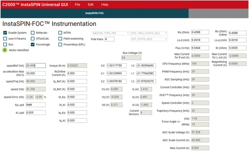
Figure 5: The InstaSPIN-FOC GUI shortly after it identified a motor. (Image source: Jacob Beningo)
Notice in Figure 5 that there are several values that have been populated in the upper right-hand corner of the GUI. These are the motor parameters that should be recorded so they can be used later to drive the motor in torque or speed mode. You’ll also notice on the left side that the “Motor Identified” indicator has turned from gray to green. At this point, we can now control the motor speed directly through the GUI.
The motor speed is controlled by simply changing the speedRef(Hz) box on the GUI. Note that motor acceleration through this reference control is very fast. Deceleration on the other hand requires entering multiple setpoints that are at a lower and lower speedRef. The motor can be completely stopped on a dime by unchecking the “Run” checkbox.
Tips and tricks for using a BLDC motor with TI’s InstaSPIN-FOC
Below are several best practices that developers need to consider when working with BLDC motors and TI’s InstaSPIN-FOC solution:
-
Select a microcontroller that has the motor algorithms built into their internal flash. This decreases the code space used for the motor algorithms and can also provide a performance improvement in their execution.
-
On the F280049C launchpad, use site 1 as the default site for the DRV8323RS Launchpad Booster pack. Using site 2 will require making updates to the software.
-
Set aside time to walk through all 13 example labs that are provided as part of TI’s MotorControl SDK. These labs cover everything from identifying motor parameters to controlling a motor through speed and torque control.
-
Use the lab 5 example to find your own motor parameters. If you are using a MOTOR_TYPE_PM, make sure that you also add the following definition in order to successfully compile the lab and then use the tuned value:
define #define USER_MOTOR_INERTIA_Kgm2 (7.06154e-06)
-
Start BLDC experimentation using the InstaSPIN-FOC online GUI.
Conclusion
Driving a BLDC motor for torque or speed control can be a complex problem that can easily grow beyond the knowledge of an embedded software engineer, slowing down project development. As shown, developers working with the Texas Instruments InstaSPIN and MotorControl SDK and associated hardware can quickly and easily get a BLDC motor up and running with a very limited knowledge of controls engineering.
By: Rich Miron – Digi-Key Electronics
Digi-Key Electronics
Contact Person in English/Deutsch Language
Hermann W. Reiter
Director, Global Strategic Business Development
Digi-Key Electronics Germany
Tel.: +49 151 6286 5934
E-mail: Ez az e-mail-cím a szpemrobotok elleni védelem alatt áll. Megtekintéséhez engedélyeznie kell a JavaScript használatát.
www.digikey.hu
More Digi-Key Electronics